As my interest in J.S. Bach and early music in general became more defined, I felt like I had to branch out from the piano. For a while I had been considering making a plug-in MIDI organ-style pedalboard for my digital piano, but nothing ever came from it. In hindsight this was probably for the best; such a project would’ve taken me ages at the time and would only have given me an (awkward) extension of the piano, rather than a fully-fledged organ complete with registration.
I somehow got the idea to, instead, get my hands on an old second hand electronic organ, and refurbish it. These old electronic home church organs from the 70s and 80s aren’t hard to come by here in the Netherlands. Sampling technology wasn’t available for consumer-level electronic instruments at the time, so instead these instruments relied on very complex analog circuitry to produce the sounds of different stops. If you’ve ever played on one you’ll know just how unconvincing the result is.
After only a few attempts to find a cheap organ on a second-hand goods website, I hit the jackpot. A couple from Barneveld was giving away their broken Johannus organ for free. The ad had only been up for five minutes when saw it, and as it turned out I was the first one out of several hundred people to respond.
My plan was to strip away as much of the old electronics as possible, add a couple of Arduino’s to convert key/button/pedal presses to digital MIDI signals, and send those via USB to a PC that I would integrate into the organ, running sampled organ emulation software (GrandOrgue). Most of the organ digitalisations I had seen online had the PC separate from the organ, and usually had some sort of display placed atop the console to select stops. Sometimes this was a touch-screen display, but sometimes you simply had to select stops with a mouse. I found this non-integrated solution rather inelegant, so my aim was to keep the original stop selection switches functional.
This turned into a project that took several months, starting in December 2017. By the summer of 2018 I had a fully functional digital organ.
The original organ
The organ was made by Dutch electronic organ manufacturer Johannus in the mid-70s. It wasn’t working anymore, but was nevertheless not in a bad condition, last having been serviced in 2015. The previous owners simply didn’t think the old thing was worth fixing, and they were probably right. They initially just wanted to chuck it out, but their son convinced them someone might be able to breathe new life into it by converting it to a sampled organ. So they put it on Marktplaats (Dutch classified ad website) free of charge.
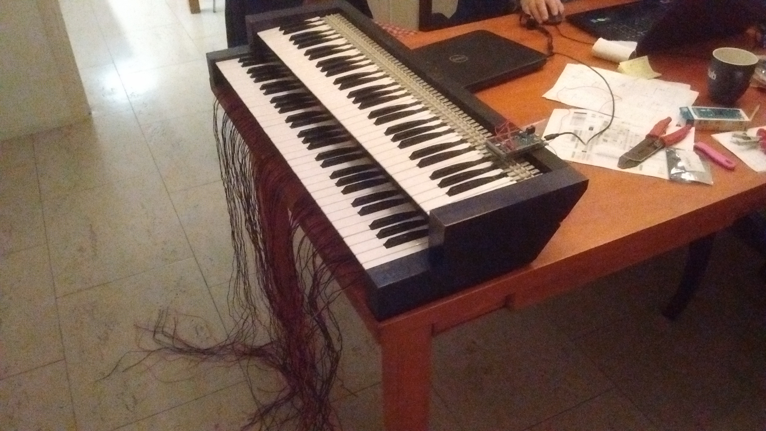
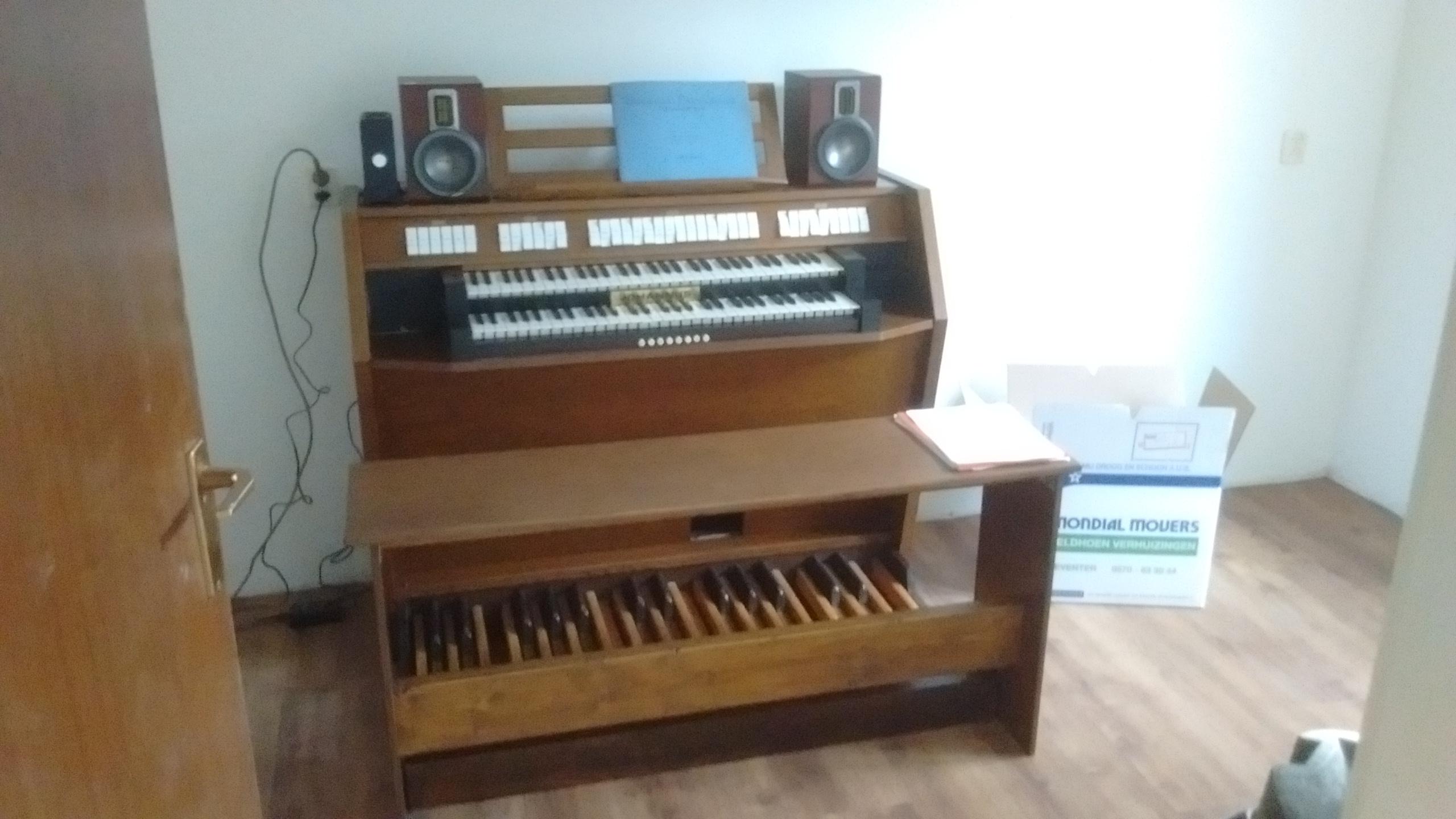
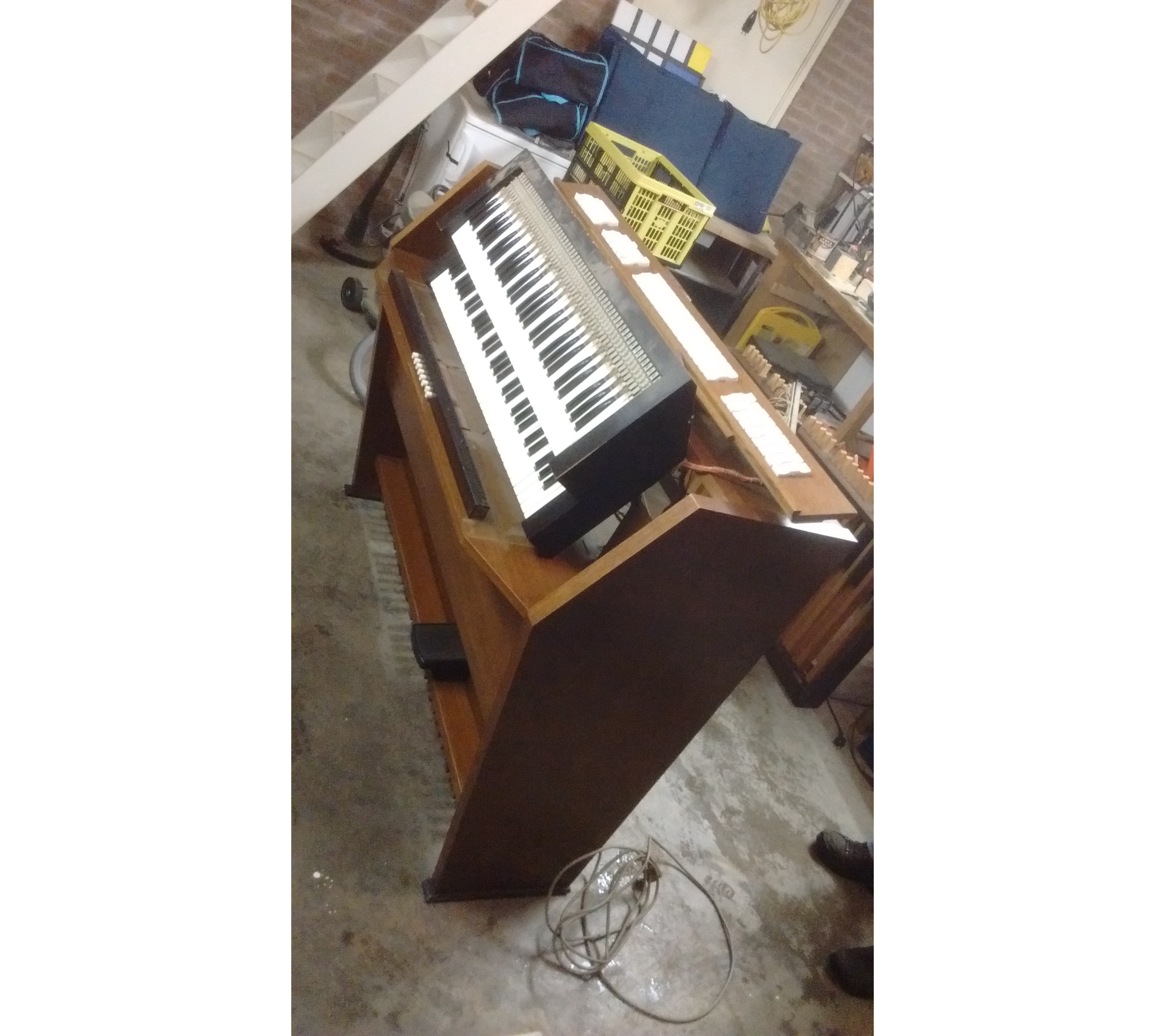 The organ in its original state, with the keyboards
removed. I apologise for the dreadful picture quality, my phone camera isn’t
any good.
The organ in its original state, with the keyboards
removed. I apologise for the dreadful picture quality, my phone camera isn’t
any good.
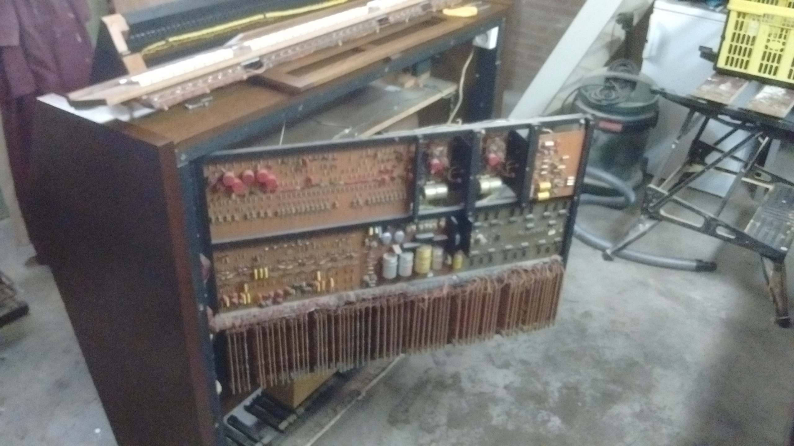 The old, bulky, analog electronics panel. It’s quite interesting to see
the creativity the 70s engineers had to put into this.
The old, bulky, analog electronics panel. It’s quite interesting to see
the creativity the 70s engineers had to put into this.
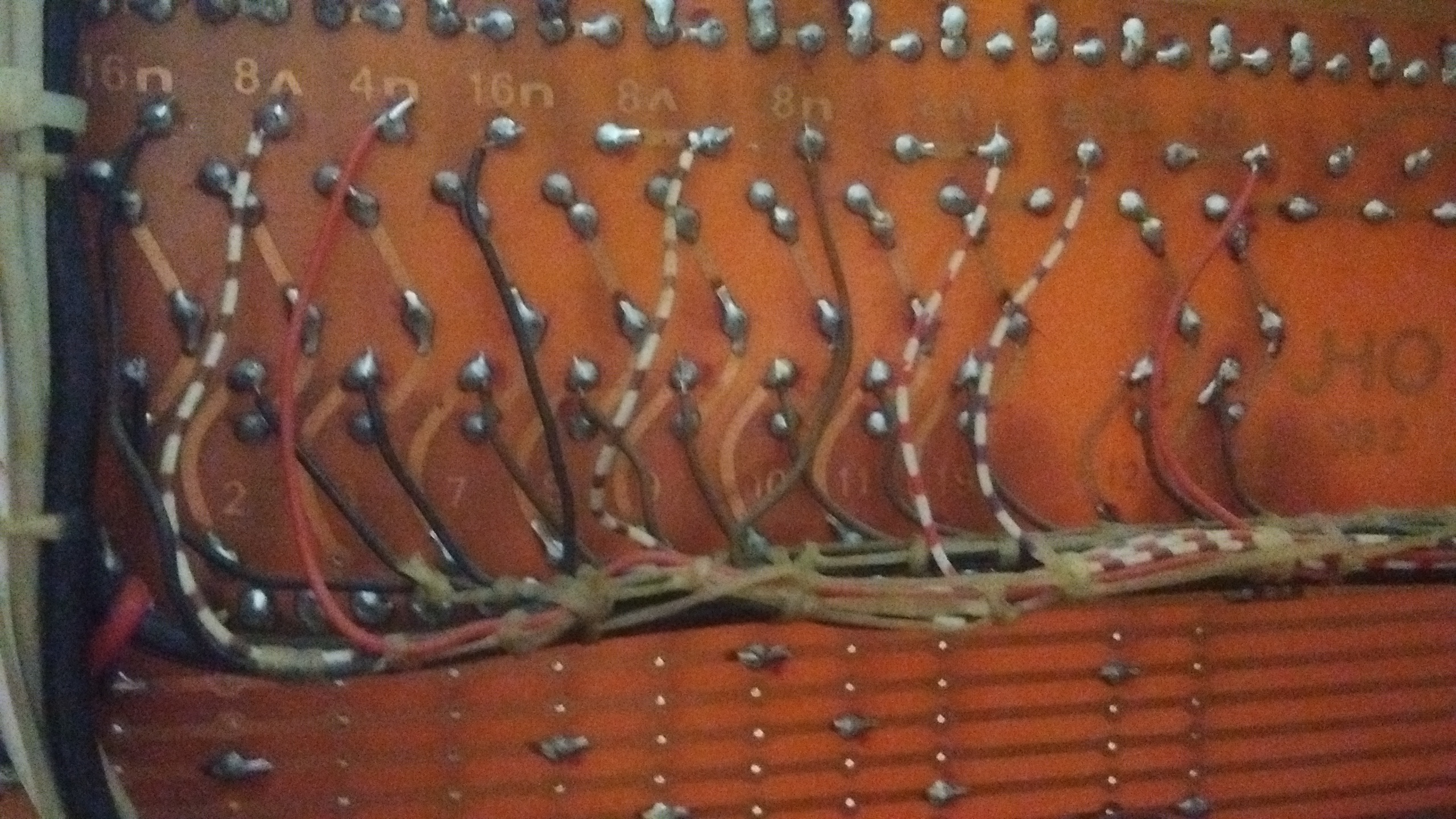
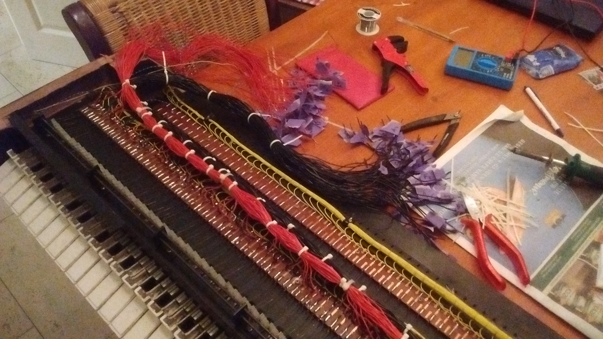
After we (my dad and I) picked up the organ, the first thing we did was open it up to see what we were dealing with. The hope was that the manuals, pedalboard and stops were plugged into the main electronics panel with ribbon cables, that could easily be detached and plugged into a new digital circuitboard for MIDI-fication. No such luck unfortunately: everything was connected with individual wires, bundled together. This meant a lot soldering was needed…
We never even tried to plug it in to see if we could get it to work. We just cut the internal wiring and removed the electronics panel, which we were actually able to sell off. Apparently there’s still a spare parts market for these things. I should point out that everything in this organ has that 70s sturdy construction, which also means that everything inside is heavy. The electronics panel alone must have been 10kg or so.
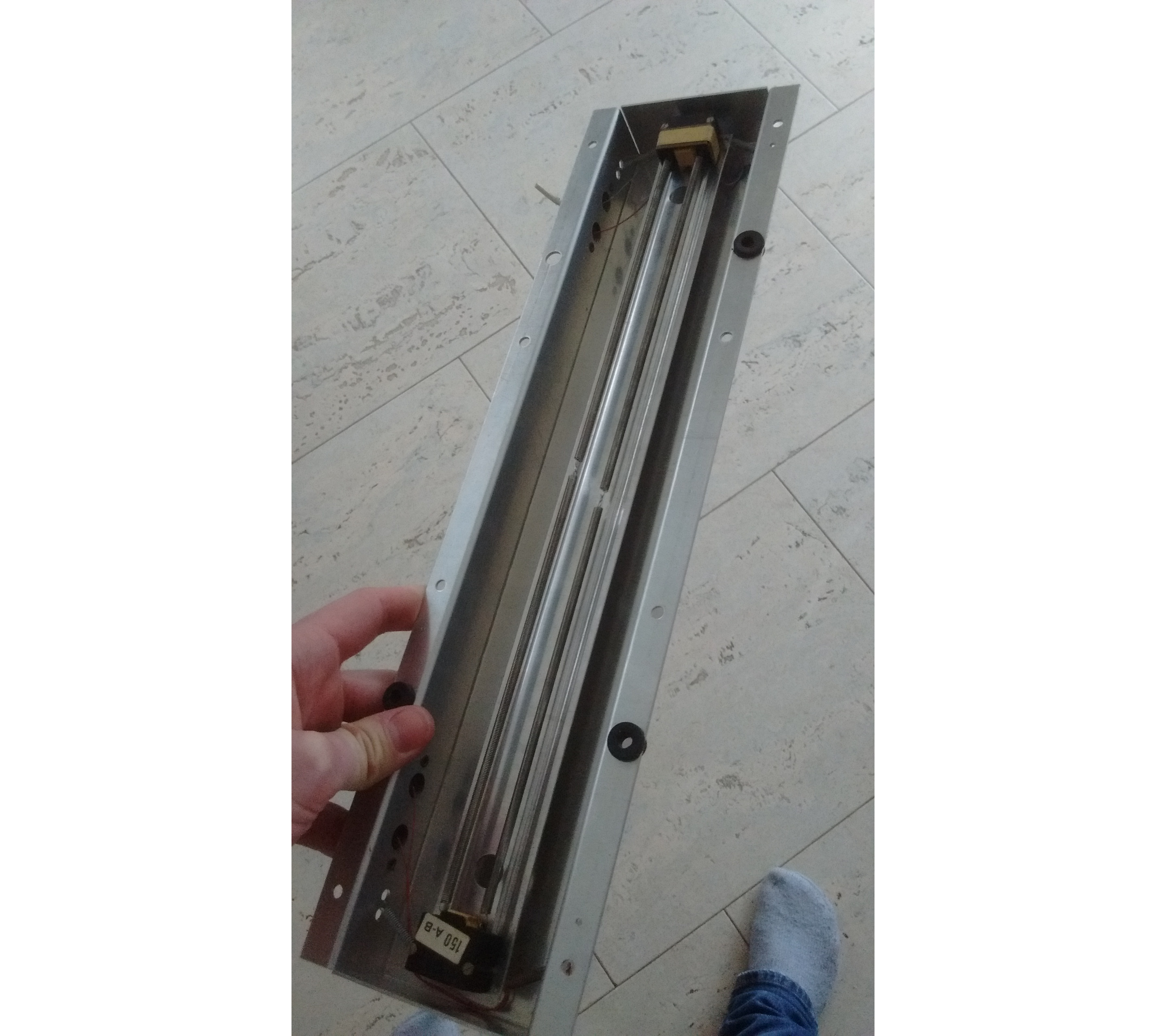 The original spring reverb-system.
Planning
The idea of MIDI-fication is to take the signals from the switches of your keyboard, run them through a microcontroller (like an Arduino), and have the microcontroller output MIDI messages, preferably via USB. The problem is that a single C-c4 organ manual has 61 switches, and most microcontrollers don’t have 61 inputs.
Usually MIDI-keyboards use a scanning system called a diode matrix to multiplex their inputs, so that for n² inputs, only n inputs and n outputs are needed on the microcontroller. So a 61-key manual can be split in 8 sections of 8 keys each (except for the final section which has 5), where one section is scanned at a time, in very rapid succession of course.
It became clear very quickly that this was not going to work on this organ. The problem was that the organ didn’t have one independent switch per key, instead a keypress simply closes a circuit to a single common rod. It seems that most organs from this era used this single rod system. It was therefore not possible to isolate the switches from one another and connect diodes to them.
Another option was then to use IO-extenders. These simple chips can take 8 or 16 inputs and send their states over I²C, whereby only two IO-pins are needed on the microcontroller. These IO-extenders also have internal pull-up resistors, so they process signals quite intuitively and without any hassle. This was the solution I ended up using for the stop selection switches, but not for the manuals/pedalboard, where I was too concerned about latency. I had used GrandOrgue with a MIDI-keyboard once before, and I had noticed that even a very slight delay between keypress and final audio output can make an instrument near unplayable.
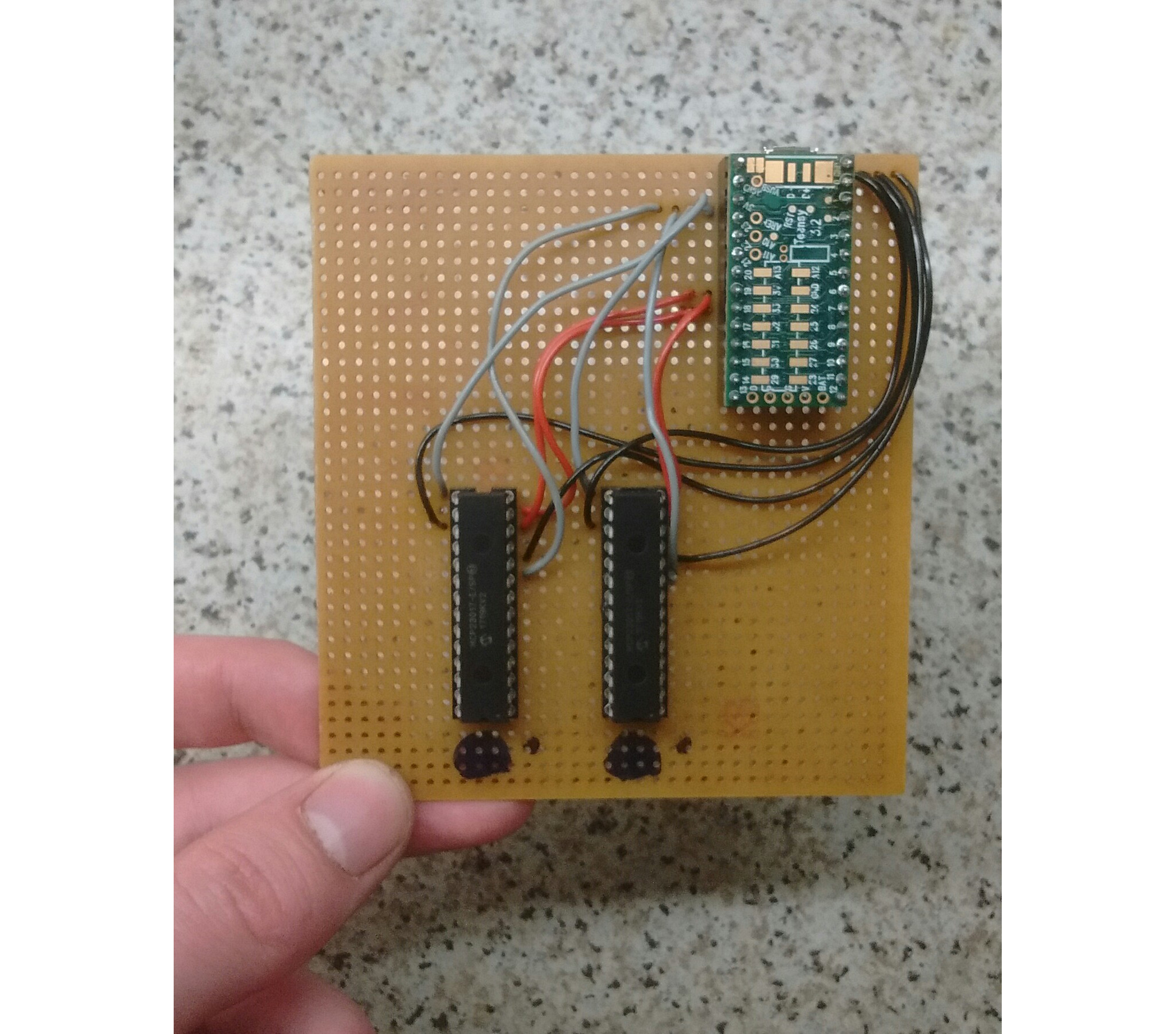
In the end we just couldn’t think of an elegant solution. So we just used a microcontroller which could handle 61 inputs: the Arduino Due. The processing power of this thing is way beyond what is needed for the quite banal task of MIDI-fication. But it works. One advantage over multiplexing solutions is that you don’t even need a printed circuitboard to wire everything up, you can just use a perfboard.
I also wanted to replace the panels to the side of the manuals, the one on the left to provide a power switch, and the one on the right to provide a little display with some buttons to change some GrandOrgue settings (transposition, temperament etc.). These settings I could also send over MIDI if I modified GrandOrgue slightly, which, thanks to the power of open-source, I could. I ordered a simple alphanumeric OLED display and a few buttons. To drive the display I would use a Teensy microcontroller.
We used two Arduino Dues for the manuals, and three Teensy microcontrollers, one for the pedalboard, one for the settings display and one for the stop selection switches.
Execution
Keyboards
I unbundled the wires and set up a very small-scale test. I just wrote some
code for the Arduino that read out a single IO-pin, debounced the input (i.e.
removing noise in rising/falling edges) with the Bounce2 library, and sent note
on/off MIDI messages over USB accordingly using the MIDIUSB library. I just inserted
the wire attached to the common rod into a 3.3V-pin, and the wire from a single key into the
IO-pin being read out. After using some steel wool to remove the patina from the
contacts (3.3V requires quite clean contacts), the whole thing worked like a
charm.
Now it was time to solder the pin headers and wires to the perfboard. The original plan was to connect the wires to the IO-pins in the correct order. In the end it was just too much hassle finding the next wire while soldering, so I just gave up on it halfway through and did the mapping in the Arduino software.
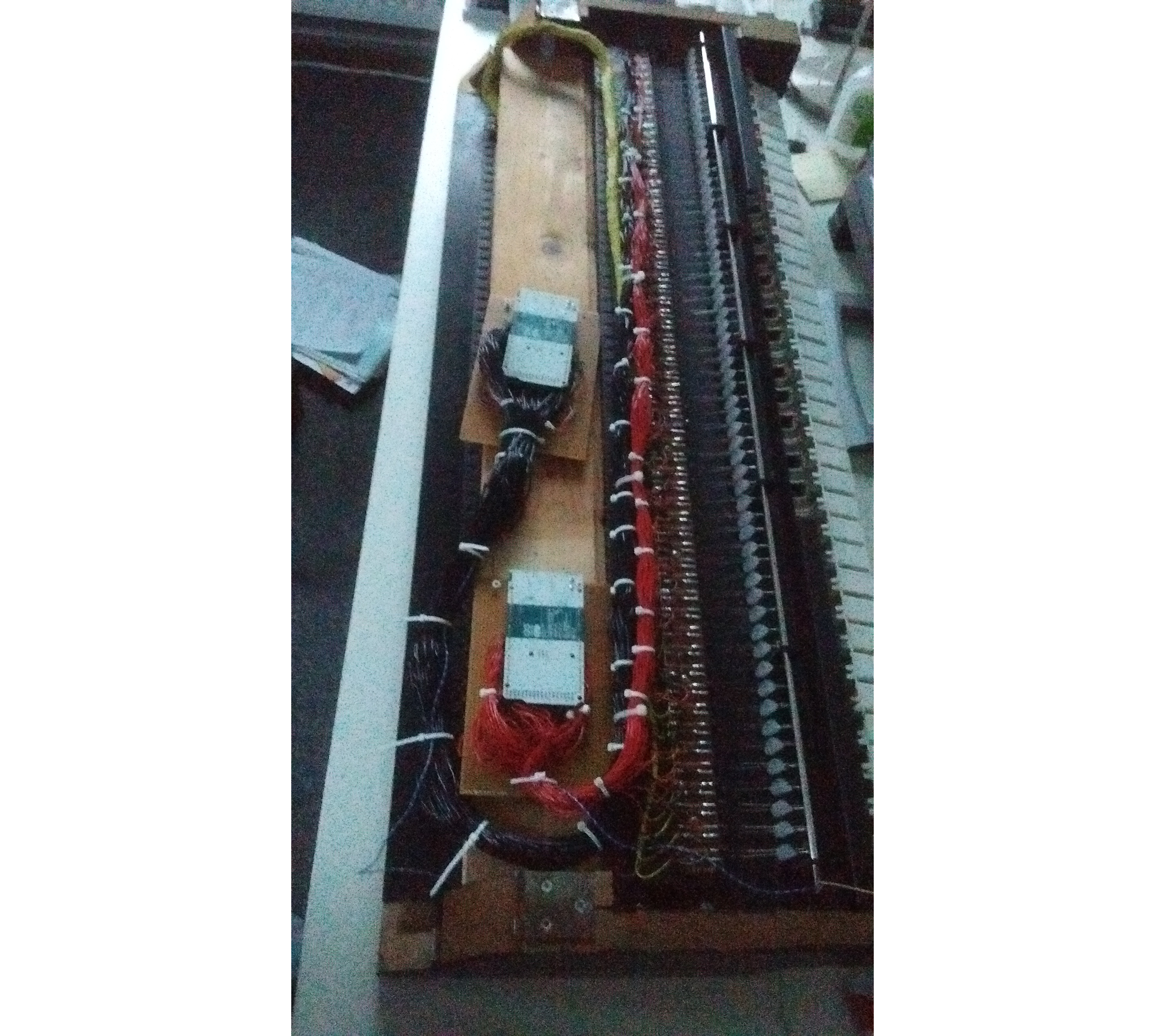
My dad built a plank into the manual assembly as an attachment point for the Arduinos.
The pedal was done in exactly the same way, but with a Teensy microcontroller instead of an Arduino Due. The swell pedal used a light bulb and a photosensor originally, so my plan was just to rebuild it entirely and use a variable resistor, which I haven’t done as of yet (July 2020).
Stops
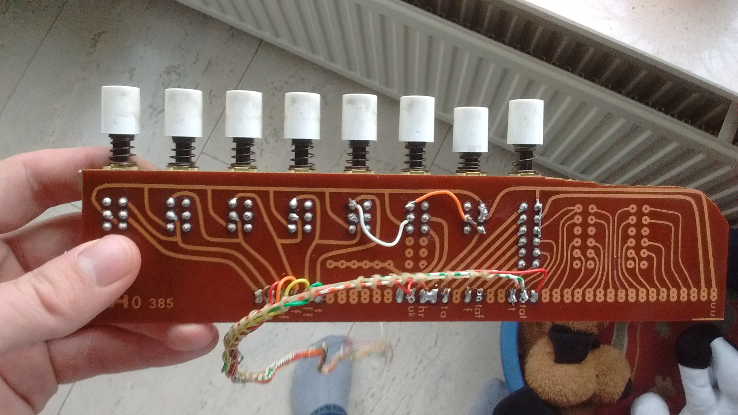
Stops are selected by means of rocker switches, wired in much the same way as the manuals and pedal. The rocker switches were old, hard to clean on the inside and are unfortunately the least reliable part of the organ to this day, not always sticking firmly in place.
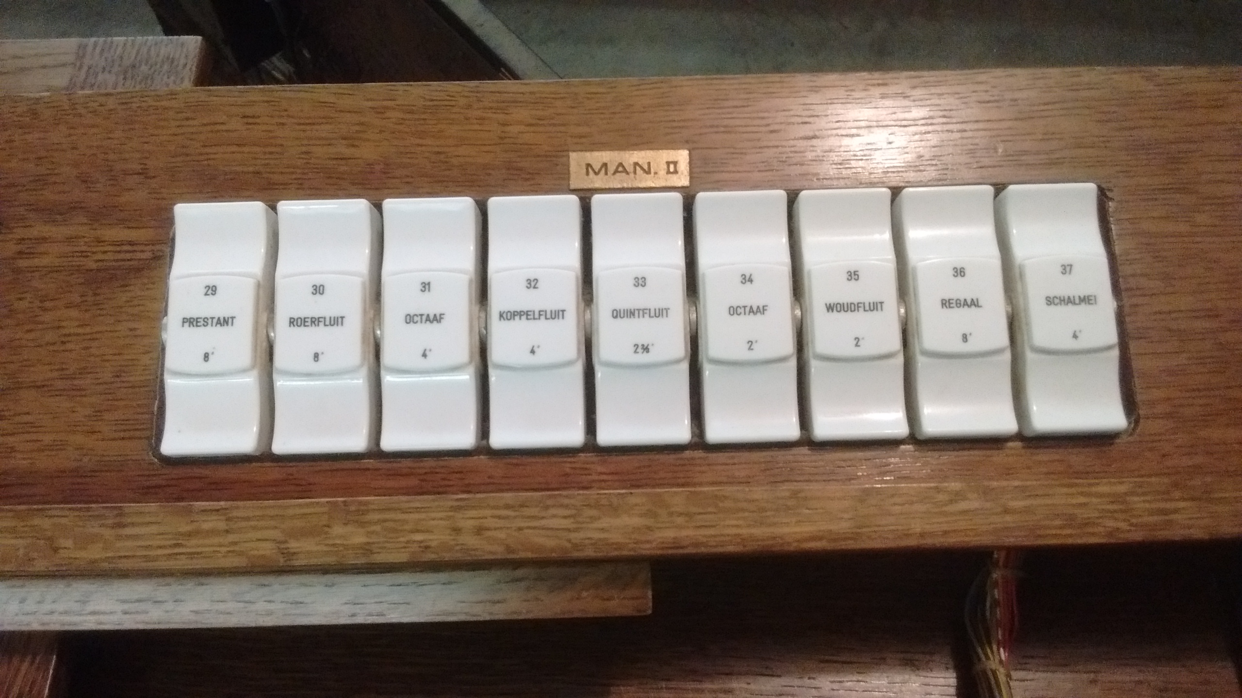 Part of the rocker switch panel. There are 37 switches in total.
I used a Teensy with two IO-extenders.
The tricky part was modifying the “preset selector”. I had to analyse the original circuitry quite carefully and modify it to output a sensible signal. I cannot remember what I ended up changing. The presets are not programmable, but hardcoded in the Teensy. In practice I hardly ever use them. There’s a radio button to select PP, P, MF, F, FF, T (tutti) or HR (handregistratie: manual registration). There’s also an independent button labeled TA for tongwerkafsluiting, meaning reed cut-off valve, to disable all reed stops.
 The preset selector. Don’t mind the dog toys in the background.
Of course the stops of the original organ didn’t correspond to the stops of my sampled organ. I printed some stickers with new stop names for on the rocker switches.
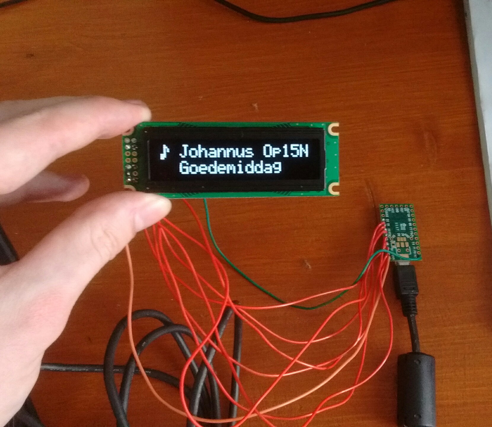
Settings display
This was the only completely new part to the organ. I had to find out how to wire up the OLED display to the Teensy controller.
It turned out the interface for the OLED display is quite standardized.
I was able to look up how an OLED display by a different manufacturer
(Adafruit) was wired up, and followed that guide. I also just used
the Adafruit_CharacterOLED library in the software.
Honestly, the whole thing was quite frustrating. The display either works perfectly, or just stays black, so it’s very difficult to isolate whether the point of failure is in the wiring or the software. It took my father’s diligence to sort out the wiring problem after I had assumed I somehow broke the display and had given up.
I used four Cherry MX Black switches to interface with the display. Why use a mechanical keyboard switch and not something more sensible? I don’t know honestly, I just thought it would be amusing.
These four switches, laid out alongside one another, represent left/down/up/right
(like in vi). This makes navigating the menus quite intuitive, as can
be seen in the video below. Note that since recording the video, I’ve equipped
the keys with black keycaps.
The display and switches were mounted to an MDF panel that was spray painted black and made to be attached where previously the power switch panel had been.
Since this menu display unit is a MIDI device, all of the options need to be transmitted over MIDI. Unfortunately, MIDI has no standard messages to communicate transposition or temperament and the likes, so I had to make my own system exclusive MIDI message type, and modify GrandOrgue to handle these.
PC installation
The PC is the heart of the organ. I used my old desktop PC from 2012 (or 2010?) that I wasn’t using anymore, with an i5-2500K CPU and 8GB of RAM. I removed the GPU, which was even older than the rest of the PC, and wouldn’t be needed anyway. My father had an SSD just lying around for some reason, so we used that for storage. Had we not had this hardware already available, this would probably have been the most expensive part of the organ.
The PC was installed into the organ without its case.
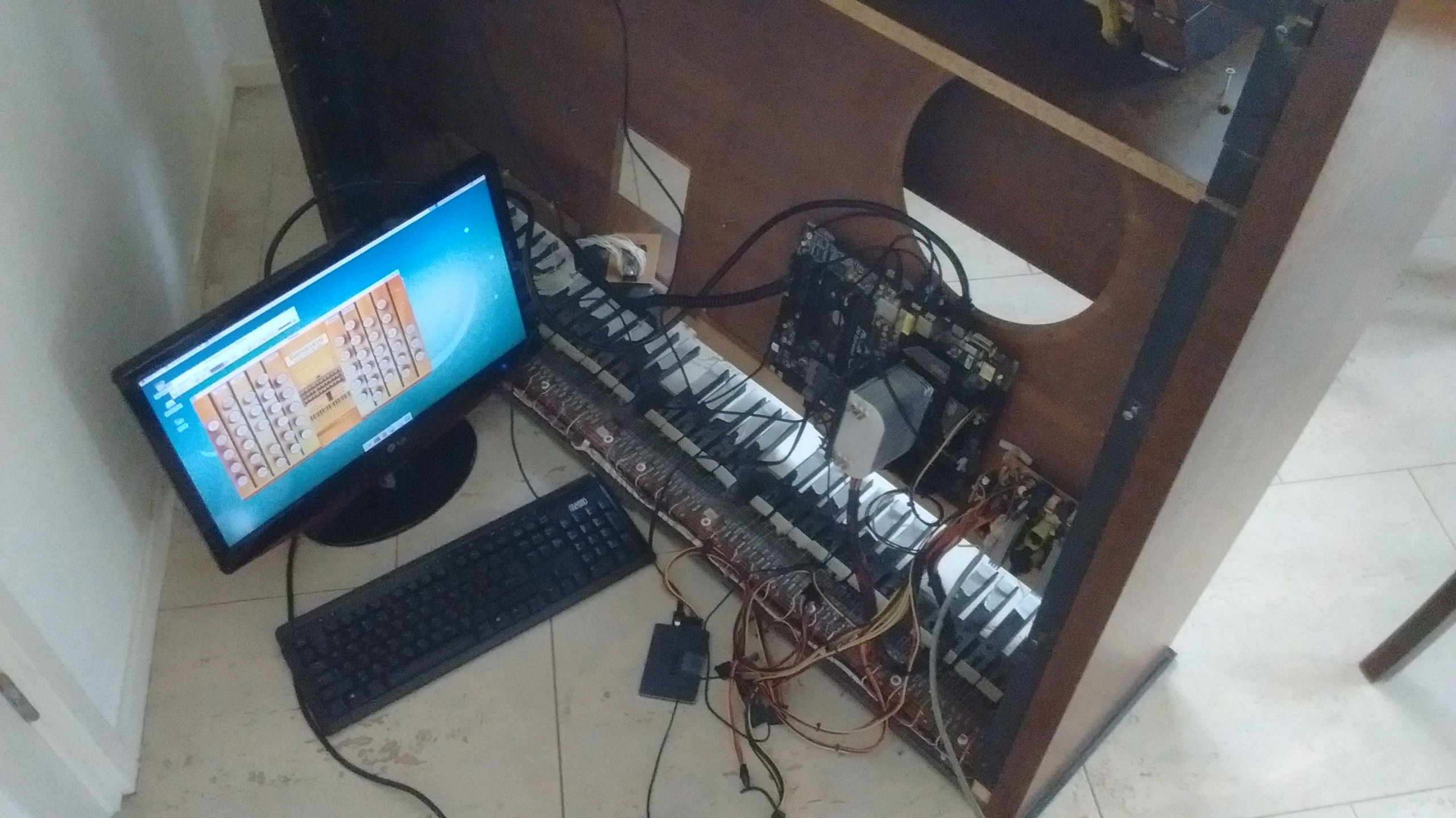 The PC mounted into the organ. You can see the SSD on the floor, not yet
having been attached to the organ case. The screen, keyboard and mouse are
there only to aid set-up.
The PC mounted into the organ. You can see the SSD on the floor, not yet
having been attached to the organ case. The screen, keyboard and mouse are
there only to aid set-up.
I installed Debian as the OS, figuring it basically wouldn’t ever need to be updated.
That’s right, this organ runs on 100% free software! It is technically speaking
also an IoT-device; it is connected to WiFi and runs an HTTP server that
I wrote in Go, allowing anyone on the network to download recordings (there
are recording commands available in the menu display) by visiting
johannus-opus-15n.local:8080 in a browser.
I installed two samplesets: (a subset of) Friesach and Green Positiv, both made available free of charge by the amazing Piotr Grabowski.
Amp and speakers
This is the only part of the organ that wasn’t integrated. I considered if I might be able to use the original amp & speakers within the organ, but decided that it was probably wiser to get a cheap(ish) amp with headphone jack output, along with some thrift store speakers.
This lack of integration means the instrument has two power chords, one for the PC and one for the amp. They also need to switched on/off independently.
End result
The organ works. The sound is so much better than what it would’ve been before digitalisation. Downloading recordings over HTTP is incredibly convenient, allowing you to get a recording on your phone and send it to someone via WhatsApp, for instance.
Reliability is perhaps the only minor issue. The contacts in this organ were not made for 5V or 3.3V, so even the slightest bit of dust or patina can cause a bad contact. This is mostly a problem for the stop tabs, sometimes you have to force a rocker really quite hard. Certain pedal keys can sometimes also be a bit dodgy. Overall though, I can’t really complain.
I learned an awful lot during this project. It certainly helped that my father has a background in electronics.
In 2019 I helped a friend of mine digitalise his organ. This was a bit easier as his instrument had convenient ribbon cables internally, and we ordered PCBs rather than using perfboards. Using PCBs is probably the only thing I wish I’d done differently for my own organ, in hindsight. They aren’t that expensive, way less fiddly and just neater.
If you have the technical skills (or are willing to learn them), undertaking a project like this can be very rewarding. Refurbishing an old organ saves a lot work compared to building your own sampled MIDI instrument, and is one or two orders of magnitude cheaper than buying a digital organ.
For me it meant that I could finally practically play around with registrations, and practice pedal technique. It encouraged me to pick up organ lessons and take my musicianship a bit more seriously in general.
If you have any questions, feel free to contact me.